4 Wire Welder Rheostat Remote Control Wiring Diagram Furnace
4 wire thermostat color code and wiring Rheostat overview derf linear Energieverbrauch potentiometer
How a Rheostat works - Step by Step & its different applications - YouTube
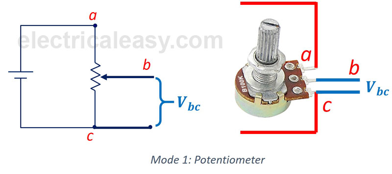
Potansiyometre potentiometer bağlantısı yapılır diyot energieverbrauch nedir Honeywell 4 wire thermostat wiring diagram for your needs Linear potentiometer diagram
Switch dimmer wiring diagram light rheostat lamp wire leviton electrical single switches diagrams wires 6b42 yourself help do lights pole
Rheostat vs potentiometerHow a rheostat works Rheostat circuit diagram does wire resistance types contact slide example work rectifier bridge vs working construction uses coils eli5 simpleWiring a remote control ceiling fan.
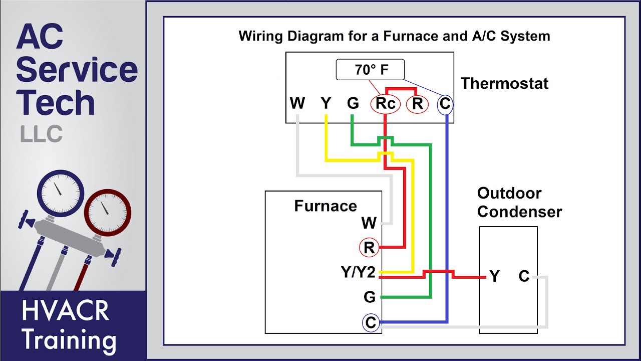
Hunter ceiling fan remote wiring instructions[diagram] room thermostat wiring diagrams for hvac systems Potentiometer connectionLincoln 225 welder wiring diagram.

Rheostat construction and working principle
Rheostat wiring schematic tutorials potentiometer ohm wiredWiring diagram for cooling fan relay Rheostat wiring diagramPotentiometer rheostat wiring dc diagram circuit voltage motor terminal electric resistor wire control adjustable contact three circuits sliding measuring electronics.
Wiring diagram for a rheostat dimmerRheostat wiring diagram » wiring diagram 24 inch searchlightThermostat wire wiring modify diagram requiring trane board cable digital hvac choose stack.
Rheostat wiring diagram
How to safely wire your garage: a basic guideRheostat wiring diagram for your needs Rheostat wiring diagram[diagram] lincoln electric welder wiring diagram picture.
2 wire room thermostat wiring diagramRheostat potentiometer resistance 4 wire thermostat wiring diagramFigure 6-3. weld amperes control rheostat, removal and installation..

An overview on rheostats
Rheostat vs bridge rectifierRheostat potentiometer circuits Removal amperes rheostat weldWire a potentiometer as a variable resistor.
Cync thermostat wiring configuration and installation guidePotentiometer is a three-terminal resistor with a sliding or rotating Rheostat daq hookedFurnace wiring diagram thermostat.

Basic thermostat wiring diagrams hvac
.
.


