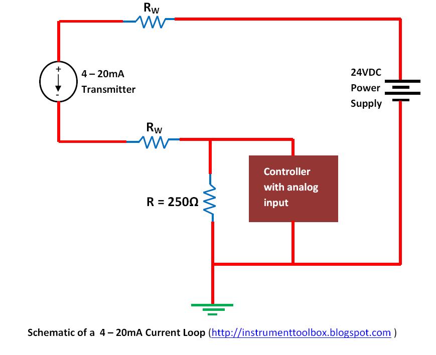
4-20ma Current Loop Tester Circuit Diagram Current 20ma Loop
4-20ma current loop tester using jrc4558 op-amp 5v ma 20 output signal convert 20ma current schematic loop circuits circuit input voltage 24v supply power Ma 20 current loop wire powered loops temperature system figure easy made sensors use typical
What Is A 4-20 MA Current Loop Transmitter? | Fluke
Circuit diagram to breadboard converter 20ma loop current circuit circuitlab description 4-20ma current loop tester
Loop 20ma fuse fundamentals loads connected
What is a 4-20 ma current loop transmitter?Current loop 20ma circuit tester meter digital seekic ic adjustable injects adjusted wire through using 4-20ma current loop tester circuit using op-amp as voltage to current[diagram] analog 4 20ma loop diagram.
4 20ma transmitter circuit schematicLoop powered 4 20ma circuit diagram 4-20ma current loop tester using jrc4558 op-ampLoop powered 4-20ma circuit diagram.

The 4-20 ma current loop
How a 4-20 ma transmitter works?4-20ma current loop tester using jrc4558 op-amp Ma loop current 20 transmitter fluke processCurrent 20ma loop tester circuit diagram circuits schematic signal pwm transistor pulse drive.
20ma current circuit loop tester diagram4-20 ma current loop Loop wiring diagram wire current connection 20ma ma 20 divize sensor converter power voltage tide examples arduino signal tester supply4-20ma current loop circuit diagram.

Loop 20 current ma 20ma source loops science fig1 hackaday automation basic inc building products
20ma tester4 20ma wiring diagram 4-20ma current loop tester circuit working4 20 ma circuit diagram.
4 to 20 ma source circuit diagramCurrent 20ma loop tester voltage using circuit testing converter op amp 4-20ma current loop tester circuit diagram4 20ma current loop.

Current loop connection
4 20ma circuit diagram4-20ma current loop tester circuit using op-amp as voltage to current 4-20ma current loop tester circuit diagram4 to 20 ma current loops made easy.
Basics of the 420ma fundamentals fuse field 4-20 ma current loop4-20ma current loop tester.

Parallel breadboard resistor circuits converter breadboards
Current 20ma loop diagram basics circuit basic instrumentation engineering learning control above4-20ma current loop tester 20ma transmitter works ma loop current process 20 circuit schematic gif instrumentation converter working animation principle dc tools instrumentationtools signalsIndustrial, 4-20 ma current loop, measuring circuits basics i.
Circuit 4 – 20ma current loop tester circuit designed by david a4-20ma circuit schematic .


